Tuesday, March 26, 2024

Page Forty-Nine - Stop and Steer


It’s been a minute, but here’s what I’ve been up to.

Disc Brake Calipers

It might surprise you that sixty years, with however many of them spent outside or in various soggy environs, can grow gobs of rust, shocking I know.  Alphie’s calipers were pretty much frozen with rust, but the Organ Donor’s were abjectly fossilized.

Rusty with one piston freed.  The other piston is solidly stuck!

With enough leverage and skinned knuckles, I was able to pry Alphie’s calipers apart.  And I thought I would break down the Organ Donor’s for extra parts, at least for the bolts, silly man.  But no amount of force was breaking apart what chemical reactions had welded together.  The Organ Donor’s calipers are ballast at this point, blunt murder weapons.

The hardest part was freeing the pistons from their holes.  As you may know, whereas modern disc brakes use floating calipers (meaning they slide on pins, allowing them slide back to center after each peddle push), Alpine calipers are fixed using a piston on each side of the disc with a balance port between the caliper halves to equalize the hydraulic pressure, which is how they re-center.

Now, if a piston is stuck, you can use air pressure to push it out.  BUT after one piston busts loose (which it did rather violently, making one Alpine mechanic jump a wee bit and make noises), the other piston stays comfortably snug in its hole.  The air pressure now simply vents out the hole where the freed piston once lived.

I tried various methods of holding the free piston in place to get air pressure to the other side, but to no avail.  Finally, and because I could see that the old pistons were manky and because I could order shiny new stainless-steel ones, I decided that drilling a hole in the stuck ones (remember, there are two calipers) and tapping them with threads offered the best chance to free them from fossilized bondage.

I drilled and tapped threads in the hole.
A bolt pushed the piston out where nothing else would

My concern was that I would 1) drill through the piston and into the caliper wall, 2) strip the threads, requiring me to drill bigger holes and 3) muck up the bottom of the piston holes with a bolt pushing out the stuck piston.  As it happens, 1) I didn’t drill into the caliper wall because I was watching it very closely, 2) the threads held dutifully, and 3) neither the drilling nor the bolt pushing against the caliper wall mucked up anything.  Go team me!
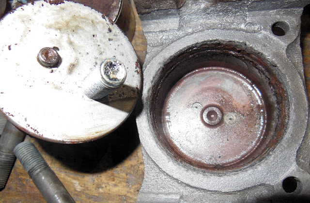
I sacrified the piston, but there's only a small scar on the caliper bottom

With lots of bead blasting, powder coating and cast-iron paint (because the color of the cast aluminum powder was too bright for my tastes), the calipers are happily clean and ready for new pistons and gaskety sealy parts.  (The shiny ss pistons are backordered, but when they get here, everything will be spanking!)

Brake Servo

Power Brake Booster for my American readers.  Brake fluid is icky stuff; it corrodes almost everything it contacts, collects water, turns to jelly, and generally makes a bloody mess.  Tearing down the servo takes many rags and a few spray cans of brake cleaner.

Just a heads-up, there’s a big spring in the can part of the servo that, when you loosen the last screw on the backing plate, will shoot everything out the back, making your favorite mechanic jump and make noises, again, just FYI.  And there’s usually loads of smelly old brake fluid in there from decades of leaking seals.  It smells terrible too.

Grungy and gross, the dissambled parts of a Girling brake servo
Cleaning everything up is gross but simple.  Removing the valves from the valve body is the big chore.  Again, the brake fluid and everything it corroded in the aluminum valve body makes an impressive glue, and the parts are small and won’t survive heavy-handed prying and banging.  I soaked the valve body with all its innards in WD 40 for a couple of days and used mostly air pressure to break everything loose.  The lower valve jumped out easily.

But the high-pressure control valve, or more specifically the end plug behind the control valve, at the back of the valve body was stuck like a mosquito in amber.  Soaking didn’t work.  Spraying copious WD 40 in it and on it didn’t work.  Brake cleaner didn’t work.  Puffing 120 psi of air pressure, nothing.  What finally worked was gently slipping a very thin feeler gauge between the valve body and the end plug O-ring braking the adhesion between the aluminum wall and the O ring’s rubber,  then pumping in lots-o-air pressure finally blew it out.  Oh, and when it finally blew out, your mechanic jumped and made noises yet again.

Cleaned painted and powder coated parts with a (second) rebuild kit
Finally disassembled, I cleaned, bead blasted, powder coated and painted all the parts (from two servos so that I had more parts from which to choose – yeah, I did the feeler gauge/air pressure, jump when it broke loose thing twice.  It went a bit easier the second time because I knew what to do.)

Another heads up, don’t cluelessly rip out the big leather seal that seals around the can because the rebuild kits don’t have a new one.  (One should at least glance through the rebuild kit before going at it.)  I had to order a second much more expensive kit that had a leather seal in it.  Thanks Harmon Classic Brakes for having a kit with a leather seal.  Eh, live and learn.

Spanking!  (We'll have to wait until I have
Alphie running to know if it works!)
With new seals, new stainless-steel hardware and slickly painted/powder coated parts, I built me a shiny new (looking) power brake servo!

Steering Box

Tearing down the steering box is simple but be sure to count the ball bearings!

The bearings at the top and base of the steering shaft are loose bearings that spray out everywhere when you take the bolts out.  I should have been expecting it, but nope.  I looked in the parts manual to find out how many bearings went where.  They’re a big pain to get back in too, just FYI.

Dissasembled and cleaned
I finally found a trick.  I would load the individual bearings for the top of the shaft and use a spring clamp at the bearing race to hold the bearings in place while I loaded the lower bearing in their race.  I used one bolt and a huge fender washer to hold the bearing race and shaft in place while I loaded it in the car.

Sporting some slick paint and powder!
So, (just FYI) with the engine and front suspension in place, you can’t wiggle the assembled steering box, shaft, and outer shaft sleeve into the hole in the firewall, I discovered.  I had to remove the outer shaft sleeve, insert it into the firewall hole (with new grommet in place) and thread the shaft through the tight space between the engine and wing (fender) well and into the outer shaft sleeve to get the steering box nestled into its bracket on the frame.

Sparkling and finally in its spot
With one bolt through the steering box and into the bracket, I removed the bolt and fender washer, slid the outer shaft sleeve in place and fitted the three 5/16” bolts to secure the whole thing back together.  By the way, fit the steering column into its bracket under the dash before tightening all the bracket bolts because I had to wiggle the steering box in its bracket to get the steering column seated in the right place under the dash.  It’s the little stuff that makes ya crazy(er).

Installed and ready to impale
Next, I’ll tell you about getting fossilized U joints out of a drive shaft that sat under a tree for thirty (plus some) years.

Thursday, February 8, 2024

Page Forty-Eight - What a Knob


A focal point of floor shift cars is the gear shift knob.  And like most junk junkies, I love easter egg hunting in consoles, glove boxes, boots, the mysterious abyss under seats, moldy boxes, and other dark nooks and crannies in old cars.  I found a collection of Alpine shift knobs in Alphie and the Organ Donor.

The original knob is a black Bakelite affair, slightly green and grungy with age.  It has the shift pattern, a good thing, but it’s as boring as golf on the radio.  Not my first choice, but I gave it a good cleaning and shine, and I must say, it came back much better than I thought it would.

The original Bakelite knob
I forgot to take a before pic, sorry
Screw a stud into the knob - this one is off the head
("Screw a stud into the knob," it's too easy.)

Chuck it up in the drill press (pillar drill) to easily polish your knob
"That's what she said", again, my apologies, I'm still 13 years old
I will probably throw it on for judged shows because stock sometimes grabs an odd point (although with a walnut dash, very UN-stock, it probably won’t matter.)

I found two aftermarket knobs in the bottom of a console or buried in a glove box; both are wood with foil Rootes emblems under murky plastic lenses.  When they were new, they were probably quite spiffy, but time and neglect haven’t treated them well.  But they gave me an idea.

Assorted shift knobs unearthed during Alphie's tear down
(Except the one on the left, which Mike made) 
The foil Rootes emblems were tattered and crumpled, but I bought a Rootes logo lapel pin when I ordered the replacement keys from Triple C Motor Accessories.  The lapel pin is smaller than the foil inserts, so I couldn’t just replace the foil with the pin.  But my neighbor Mike is an accomplished wood turner, really his stuff is amazing, so…

With one of the wood knobs with the shape I wanted and the lapel pin in hand, I moseyed to Mike’s house and asked him if he could turn a knob similar in shape, but with a hole in the top the diameter of the lapel pin.

For Mike, this was a 15-minute job.  The only catch was that he had to order a 5/16” X 24 insert (fine thread, of bloody course) to match the gear lever.  After a quick turn on the lathe, Mike forstner bitted a hole in the top of the knob exactly the diameter of the lapel pin.  And Bob’s Your Uncle, it is as perfect as I knew it would be.

Chunk-o-Walnut chucked up in Mike's lathe

Rounded out

Mike matched the shape of one of my "found" knobs
He oiled the walnut, hence the color change

PERFECTION!
Since I don’t have a chintzy clear plastic lens to cover it, I planned on a two-part resin that I see folks using to make all manner of craft projects to do the trick.  The stuff’s expensive, about 30 bucks for two 4-ounce (118 ml, for the metrics among us) bottles!

With the lapel in place, before adding the resin
I wish the resin had turned out this clear
Mistake: I wanted to reproduce the convex shape of the chintzy plastic lens, so the resin would need to be higher than the top of the knob.  The resin would settle into a flat plane at the tip of the hole.  I had a paper circular gasket from something somewhere that I taped surrounding the hole so that the resin would settle higher than the surface of the wood.  Solid plan, but the resin is the best glue ever, and I had to sand through the gasket since it wouldn’t just pop off like I had planned.

I found a threaded rod with 5/16” X 24 threads (I think it is one like the studs that hold the thermostat housing on the cylinder head) and chucked it up in the drill press (aka the pillar drill for the Brits).

With it spinning merrily along, I could sand the resin down to shape, and with continually finer sandpaper, I smoothed it out and the resin slowly cleared.  Wet sanding with 3000-grit smoothed out the resin, but it was still a bit cloudy.

Mothers Mag & Aluminum Polish parted the clouds in the resin and gave everything a pleasing shine.  Now you can see the tiny bubbles that didn’t float out during curing, alas.  (I need a vacuum pot to get all the bubbles out, note for the future.)

This close-up shows the tiny bubbles in the resin
The spots on the walnut is the woodgrain
Some wipe-on polyurethane and some paste wax, and Alphie has a custom shift knob, and what a knob it is!

Friday, January 19, 2024

Page Forty-Seven - Suspended Progress


This is how it goes when resurrecting dead cars; you spend 95% of your time restoring individual parts, only 5% actually building the car.  

I painted the car, true, but it’s too damn cold to wet sand anything, so I decided to install the wiring harness.  I positioned the harness in the body but found that the dash locates it, which means I needed to complete the dash, so I did.  But installing the dash would be stupid because all the sanding and polishing threatens my lovely burl walnut dash.

So, I figured I would install the rear suspensions.  Which means I needed to measure and bend the hard brake lines on the rear axle.  Which means I needed to prep and paint all the rear brake hardware.  Then I found that I couldn’t finish the brake lines until I ordered new wheel cylinders…  I think you see how this is going. 

Since I’m restoring the rear suspension, may as well do the front suspension at the same time, right?  Only logical...

Prepping and Painting Suspension Parts - the axle housing took a lot of elbow grease, putty knives, scrapers, and thinner soaked rags to cleave 60 years of oil-caked dirt before I could unleash the sand blaster on it, not the indoor bead blaster, mind you, but the outdoor, siphon fed one that blows grit into places you don’t know you have.

Where we started

After scraping, cleaning and sand blasting

After painting with Eastwood's Extreme Chassis Black
(It looks better than my photo shows, I promise.)

The rest of the hardware, including the front suspension A-arms and assorted hardware took TIME and much compressed air.  Each piece required a minimum of two sessions in the bead blaster, most took four or more.

The pivot arms of the front upper and lower A-arms had to spend several hours in rust dissolver, then several sessions in the bead blaster.  The air compressor is tired!

Half cleaned: pic shows the blasting sessions to bare metal
(The backing plate is powder coated.)

All but the A-arm is powder coated
The A-arm is Extreme Chassis Black rattle canned (needs another coat)

The powder didn't stick well to the upper A-arms
Should have blown off the powder and spray painted it

I first applied the powder coat primer (grey).  The black powder
didn't stick to the primer - I think because the primer insulated the metal

The leaf springs only sucked a little.  The hardest part was pushing the old bushings out, actually holding the spring while holding the “pushing parts” (sockets and whatnot) in place and pumping the press jack.  Rust requires persuasion!  Yeah, the rubber part pushed out easily, but the steel outer sleeves were tough.  I finally found the right combination of ½” sockets, metal plates and hunks of steel and pipe to break rust’s formidable grip.  Cleaning them was easy enough.  I clamped them down, slapped a wire cup to my 4” grinder and had a time with them.  Some lacquer thinner finished the job.

The bushings before I started pressing them
It doesn't show in the pic, but I marked where the bushing offset goes
The rubber parts press out easily
The bushing's outer sleeve? Not so much

Bushings, post-pressing

As it turns out, pushing out the A-arm bushings was a bigger pain, requiring all my ingenuity, my entire collection of sockets, and some yoga moves to press them out.  I had to press around the pivot bars without bending or marring the A-arms themselves.  That took a sentence to write but an entire day to execute.  AND I’ll have to press the new ones in (should be easier though, no rust, clean and slick).

Paint - I painted the big pieces with Eastwood’s Extreme Chassis (gloss) Black primer and paint.  I used the spray gun for the axle housing, front crossmember and leaf springs, but either powder coated or Extreme Chassis Black rattle canned the remaining pieces.

Eastwood’s Extreme Chassis paint is brilliant stuff, creates a cracking, shiny finish.  But it takes at least two days to dry.  I found that it still leaves fingerprints in the gloss after a day.

I powder coated as many of the suspension parts as would fit in my oven.  Powder coating is, hands-down, the best and toughest coating for parts facing the slings and arrows that undercarriage parts must endure.

Assembly is where progress ground to a halt.  Bending brake lines requires massive patience, double, triple, quadruple-checks, some luck, and the right tools.  (Measure six times, lay it out and stare at it for a LONG time, test fit it, before even contemplating cutting anything!)  Sunbeam “helps” us by making some of the brake fittings bubble flares and others double flares.  I may do a side post about how to make each, but I only had a flaring tool for double flares.  I had to buy a kit (Harbor Freight again!) that makes bubble and double flares.  And I had to learn how to manage it.  How did I restore junk before You Tube?!

I bought a brake line set from Sunbeam Specialties, so I knew I would have to bend and fit the lines.  (To be fair, nobody makes a pre-bent set of lines for Alpines.)  But I ordered the wrong kit.  I ordered the kit for early Alpines (I think), which don’t have “T” junctions on the rear axle.  Not a big problem in that I was only missing one line, which I added to my next order from Rick and the crew at Sunbeam Specialties.

It could be that I got the wrong brake line kit altogether or my Alpine is weird, but Alphie’s “T” junction requires bubble flares while the wheel cylinders require double flares.  All the flares in the kit are double flares, and the lengths are a bit long for the locations.  Since I have to re-flare the ends, it’s good to have some extra length.

Left - bubble flare, Right - double flare
(I made the bubble flare, not perfect, but it will hold pressure)

Wheel cylinder with double flare cone receiver at the hole 

Alpine junction with bubble flare receiver -  a concave dish, no cone
This is the "+" junction in the engine bay
The old wheel cylinders were serviceable but dodgy; it’s the brakes for Pete’s sake, important components, not a place to scrimp on buckage (poundage, quidage?)!  I decided that I had better wait for the new wheel cylinders before making the final bends and flares.  Just because the old cylinders use double flares doesn’t mean the new ones will, don’t bugger it up.

Here’s where things stand.  I have gobs of bright glossy suspension parts laying about waiting to be assembled, with about $800 worth of parts in shipment.  When I manage to get everything in the garage at the same time, I’ll chuck them together and suspend Alphie!

In the meantime, I think I’ll bolt Alphie’s little motor to the shiny front crossmember and fit it in Alphie’s chest.  We’ll see how many unforeseen tasks that digs up!

Some More Pics:

Leaf springs, painted with new bushings, rubber wraps
and shiny new hardware

The bubble flares, the other ends have double flares
Thanks Rootes Crew!

Alphie has a new rear end!

Shiny new brake lines - a few crinkles, but not bad

The front suspension is next with all spanking new parts!
(The chunk of angle iron on the lower A arm is to prevent smushing it
when I press in the new bushings.)


Monday, November 27, 2023

Page Forty-Six - Rust in the Tanks

(These are the Organ Donor's tanks. I forgot to take a
before pic with the others.  They weren't this rusty.)

 Like everything with Alphie, I have four gas (um, make that petrol) tanks to choose from.  The Organ Donor’s are very rusty but not dented while Alphie’s took a driver’s side smack at some point but only had minor rust.  In this case, the dents are more fixable.

First, I applied some soap, a stiff brush, and the pressure washer to remove as much of 60 years’ worth of dirt as I could.  Cleaned, the rust turned out to be mostly on the surface, sanding handled the rust on the outside, but the inside required electrolysis.

Normally, the rust part is submerged in a baking soda and water solution with a sacrificial anode pulling the rust off the rusty part.  With Alphie’s tanks, the soda/water solution is in the tank with the anode suspended with rubber tubing to prevent them from shorting against the tank.  With the battery charger connected to the (positive) anode and (negative) tank, the rust broke lose from the inside of the tank and adhered to the anode.  I left it on the charger for about 8-ish hours, and it worked wonderfully.  Now for the dents.

Driver's side tank in the electrolysis bath
Alphie’s driver side tank had a small cave in on the wing (fender) facing side, meaning, once installed, the dent isn’t visible, so I didn’t have to fix it to invisibility.  I grabbed my Harbor Freight Stud Welder dent puller kit and went crazy.

Of course, when I gave one stud a sturdy yank, it pulled out, leaving a hole in the tank.  AND of course, when I applied the MIG, I burned through the metal, then burned through again, and again, etc. as I chased the ever-growing hole in the tank.  Eventually, I found enough solid metal to stop burning through.  BUT when I ground down the welds and held a flashlight (torch for the Brits among us) I could see pin (and bigger) holes of light breaking through.  After sealing all but the smallest of the holes, I spread some JB Weld over the welds to smooth them over a bit and seal any remaining pin holes from the outside.  The tank sealer will seal the holes from the inside.

The driver's side tank. OK, so it isn't the dent repaired side because I forgot
to take a pic, but you don't see it when installed anyway, so leave me alone!
The tanks' innards were rust-free, but far from clean.  I used a combination of diluted muriatic acid, etching solution, some old chains (for scrubbing), and lots swishing about, which required more exertion and longer than I expected.  Satisfied that the innards were sufficiently clean, I dumped in a bunch of acetone (to neutralize the acid) and returned to swishing.

Ready for the sealer
Cleaned, neutralized, and etched, all that was left was blowing the lose particles out and applying the tank sealer.  I chose Eastwood Company’s Gas Tank Sealer.  They size the bottles so that one bottle will seal a motorcycle tank or tank up to five gallons.  I bought two, one for each of Alphie’s tanks.  De-rusting and cleaning the tanks is involved but sealing them is dead simple.

I used some old hose clamps and rubber gloves to block the inlets and outlets, uncorked the bottles of sealer and poured one bottle in each tank.  The instructions say to turn the tanks in all directions to ensure that all inside surfaces get an even coat of the sealer.  I let them sit for a bit, then repeated the turning process to give each side a second, and then a bit later a third coat.  With all sides showing a solid white coating, I poured out the excess, which the instructions say shouldn’t be left to harden in the bottom of the tanks.  The instructions also say that there will be a lot of excess; true to their word, I poured out 1 ¼ bottles of excess.

I painted them with Eastwood Company's Extreme Chasis Black (primer and paint).  The stuff takes forever to cure, but it leaves an awesomely shiny black!

Sealed and painted with upgraded clamps and new rubbers.
(You giggled, didn't you?  I know you did.)
Now everything needed to sit and cure completely.  I figure that it will be another year before I’m ready to fill ‘er up and crank ‘er up, so plenty of curing time.

Series IV and V Alpines have a curious (sketchy) way of connecting the two petrol tanks using three connecting tubes running through the space at the rear of the boot, just forward of the rear bumper. The petrol line attaches to the center cross-tube to transfer fuel to the engine.  Rear end collisions give me pause, and I’m guessing Sunbeam’s design probably wouldn’t pass muster under current safety regulations.  Seems at least as dodgy as the crimes committed by Ford’s Pinto back in the 70’s, but Brits OK’d it in 1964, so here we are.

Passenger side tank installed with sketchy cross-tube,
ready for a rear end collision
I decided to use but upgrade the original wire type hose clamps.  I recovered enough clamps for the mission, bead blasted, and clear painted each.  I swapped out the flat-head screws for some spanking stainless-steel Phillip’s head ones because I will abide no rust, and I really hate flat-head screws.  With new rubber hoses and tank-to-filler neck rubber, Alphie will drink clean petrol eventually, you know, once I rebuild everything else.

Driver's side tank.  I'll add the vent/balance tube
when I get the correct size and length hose.

Oh, I also ran a new petrol line from the boot to the engine bay, brilliant!  (I’ll run a new vent/balance tube between the tanks soon, just haven’t bought the hose yet.)

Tuesday, November 21, 2023

Page Forty-Five - A Dash of Burl


I Googled it, so it’s fact, Alpines didn’t leave Coventry, England with wood dashes, but burled walnut is so classy and looks brilliant!

My thinking was that I needed to lay in the (new) wiring harness before I started slapping all the other new parts on Alphie.  But the wiring harness is centered on the dash, meaning I wouldn’t know how much wiring to pull through the firewall etc. because the dash defines the harness’s placement.  So, I drug out my two dashes (from Alphie and the Organ Donor) and ripped into them.  (I’m not throwing a minty new dash into Alphie until I have made all the messes of buffing paint, installing glass, laying in interior panels etc. so that plan got shelved.)

I noticed some dash differences:

·    Some of the gauges on Alphie’s dash have down facing needles.  All the Organ Donor’s gauges have up facing needles.  They’re all Jaeger gauges so either there is a model year difference or the lads on the line slapped in whatever gauges were in the bin when an Alpine landed in their station, or someone swapped them in the last sixty years.

Some are up-facing and most are down-facing needles. 
The down-facing needles are white, the others are orange
- Both plastic dashes have one more hole than the walnut dash.  The hole is for a second turn indicator light as best as I can tell.  When I get to it, I’ll scour the wiring diagrams to confirm that.

This hole isn't on the wood dash, not sure why
 Alphie’s dash has black knobs on the heater controls whereas the Organ Donor’s has chrome knobs.  (I went with the chrome knobs because most of the pics I found online of ’64 dashes had the chrome ones, but not all.)

I think the black plastic knobs (above the dash, hard to see
in my crappy pic) go on '65 models, not sure though
The Organ Donor’s air position heater control (on the left side with a center detent) has a broken switch, which is actuated by push/pulling the stem in and out.  I suspect it controls the blower motor, but I can’t find a forum post that even mentions a switch on the control.  (I’ll look into the mystery during the aforementioned wiring diagram scour.)

The arrow points to the broken switch. The control next to it doesn't have the switch. I think it controls the blower motor, needs more research.

After sixty years, it is difficult to determine if these differences are model year (factory) differences or the result of people keeping a car on the road or Rootes just trying to get cars out the door.  I’m trying to keep Alphie sporting the stuff he was born with, well, except for the walnut dash.

After I stripped the Organ Donor’s dash down to the plastic, I knew I wouldn’t be satisfied with black vinyl, so I started the wood dash hunt.  I first asked my neighbor how hard it would be to make a wood dash with a router.  His expression confirmed my suspicions; it would be a difficult, time-consuming and costly task with lots of discarded attempts.  He took the dash panel and asked some of his wood working mates with access to CNC routing equipment what it would take.

While he was exploring that option, I launched a Google assault.  I found one on Sports and Classics: British Sportscar Parts and Restoration’s website (sportsandclassics.com).  It seems they had bought the remaining stock from a gent who had been making wood dashes for Alpines and Tigers but had shut down his business.  They had one left, an Alpine dash (open cubby, no glove box door).  I immediately threw down my money!  FYI, my neighbor reported that it could be done, but not easily and probably more expensive than what I had paid for the online one.  Perfect solution!

Gauge Rehab:

Of course, I chose the best set from the two sets of gauges and refurbishing them wasn’t that difficult.  I disassembled each and bead blasted the components that the blaster would blast to bits.  Cleaned the glass, replaced the perished rubber bits with o ring material, clear coated the housings and brackets and cleaned the dials as best as I could without destroying the lettering.

Pro Tip:  The little needles are damned flimsy so delicate touch!

I didn’t determine if each gauge actually functions because I couldn’t figure out how and didn’t want to take the time.  I’ll fight that battle later.

Problems:

Keys:  This bit of research took about a week.  I discovered what perhaps you folk already know, when you picked up your new Alpine from the dealership, they gave you two keys, one for the ignition and doors and the other for the boot and console.  Sunbeam used two manufacturers (primarily):

·         Wilmot Breeden’s Union line of key blanks (FS series keys) for the boot and console.

·         L&F (Lowe and Fletcher) or Strebor (“Roberts” spelled backwards) Diecasting (RM series keys) for the ignition and doors.

Original L&F and Wilmot Breeden keys

Very worn, only 60 years old.  I get it!

Left, the originals Right, new cut-to-number keys.
The new blanks are very similar too.

Alphie has his original keys, but they are sorely worn. Next, I journeyed to the shed to gather all the locks: four door locks, four console locks (a friend gave me two old consoles), and two boot locks.  I found the numbers on all of them and found the set that matched the numbers stamped on Alphie’s original keys.  (If I had not had Alphie’s original keys, I would have put together a set that had numbers I could have cut.)  I cleaned and oiled each lock, and they are ready for action.

With Alphie’s original locks in hand, I set to Googling again.  I found Triple-C Motor Accessories (triple-c.com) who will cut keys to a number, not copy them.  (When you copy a worn-out key, you get a new worn-out key.  Cutting them to the number gives you a new, new key.)  Now Alphie has his original keys for show and clean set of newly cut keys for motoring.

Switch Holes:  The switch holes on the wood dash are single smidge too small.  I used my Dremel with a small sanding drum to CAREFULLY open the holes a smidge.

Switch Body Reliefs:  The switch holes didn’t have reliefs cut in the back to accommodate the switch body.  When I test fitted the switches, the switch stems were inset too far to allow all three positions on the three-position switches.  I used the router set-up on the Dremel to cut reliefs behind each switch to inset the switch body forward in the dash to give the needed clearance.  (See pic)  Sorted!

The arrows show where I routed in reliefs for the switch bodies.
Heater Control Mounts:  Wood dashes don’t have the heater control mounts, and all the places where you can buy them tell you that.  It’s not a difficult fabrication.  I just made an index card template from the plastic dash for the hole spacing and basic dimensions and tweaked it as I went.  I used 16-gauge Lowes sheet metal and the mighty MIG welder to glue it together.

I had to elongate the holes to allow me to fine tune how far the heater control stems protruded from the dash, easy enough.  I found that I had to file off some metal to prevent the control stem from rubbing against the mounts, easy enough.  I tried several combinations of stacked washers to center the stems in the slot in the dash, again, tedious but easy enough.

Custom fabbed heater control mounts.

Stacks of washers to position the slider stem in the center of the opening
Heater Controls Face Plate:  The cleaned and shined gauges, smashing!  The cleaned and sorted switches and lights, smashing! The heater controls face plate, rusty, dull, and unacceptable.  A quick bead blast would clear the rust but also the lettering too.  To the Sunbeam Alpine Owners Club forums – what had other folk done?  I found “Bobbo” who had printed some (thick, as it turned out) vinyl stickers and still had some for wayward Alpine restorers.  He sends you two stickers in case you screw one up – he knows who he’s dealing with!  A bit tedious, but blimey it looks good!  Thanks Bobbo!

The blasted and painted heater control bezel and it's new lettering
New vs Old - the new one is on the top, the old on the bottom

Clock: I have only one clock, and it’s not in great shape.  I doubt it works, but most car clocks from the 60’s didn’t work by the late 60’s, if ever.  I’m not terribly concerned that it works, but the clear plastic (not glass) cover is scratched, and the numbers are barely visible. 

It is a Smiths clock, and I like it better than the clock delete badge.  Maybe I can find a better one sometime.

The clock is in meh nick.  The numbers are faded and
the plastic "crystal" is scratched, and it probably doesn't work.
Switch Labels:  I’ll get new switches labels before I install the dash, you know, those little metal hangy down bits.  Hold your horses, people!

Next time – gas tanks!